Saber
Overview
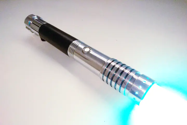
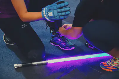
In this project, I built and customised a saber that I use in combat sparring.
In 2017, I joined The Saber Authority in Singapore, an academy for learning combat blade fighting based on the Tuhon Tim Waid of PTKGO (Kali) martial arts system. As an avid Star Wars fan, engineer and designer, I wanted to construct my own saber to use during my training at the academy.
The Version 1 of the saber has been wielded in 100+ sparring duels and at a tournament. Version 2 is a work-in-progress.
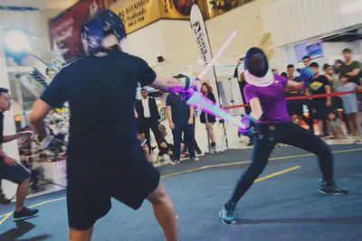
The video below shows one of my sparring duels. The objective was to “disarm” the opponent by hitting anywhere on their armed forearm or hand.
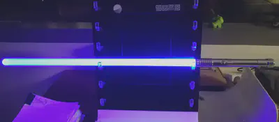
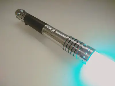
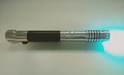
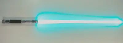
The video below shows the colour-changing function where I can cycle through different customised colour presets. Notice that the saber also has sound and lighting effects that are similar to what you see and hear in the films.
Version 1
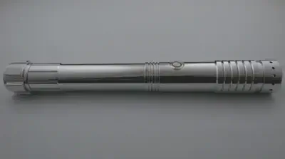
Anatomy
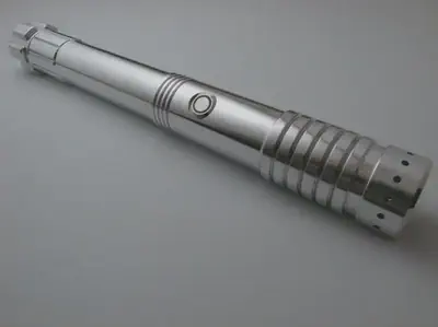
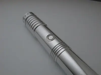
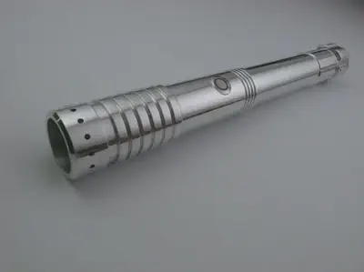
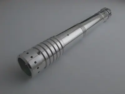
A typical duel-worthy saber comprises of the various parts as shown below.
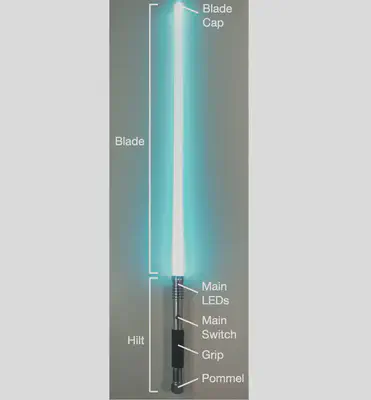
Descriptions of parts shown in Figure 1:
| Part | Description |
|---|---|
| Blade | Polycarbonate tube (same as riot shield material) with an inner reflective film to disperse light throughout the blade. The tube is typically 1" (2.54 cm) in outer diameter. |
| Blade Cap | Glued to the tip of the blade to keep the film inside the tube and it usually has a reflective material to reflect light back into the tube. |
| Hilt | Usually made of machined alumimum tube with space to fit the electronics and part of the blade. |
| Pommel | Usually machined alumimum that can be capped and uncapped from the bottom of the hilt. |
| Main LEDs | High-power LEDs with lens to narrow the light’s focus. Usually held in place with a machined copper/alumimum heatsink and holder. |
| Main Switch | Typically AV momentary switches that activate the main LEDs. |
| Grip | Leather/Cloth wrapped around the hilt. |
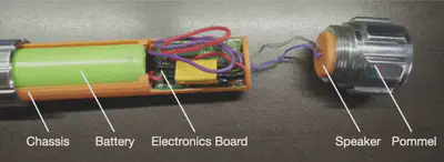
Descriptions of parts shown in Figure 2:
| Part | Description |
|---|---|
| Chassis | To hold the electronics, board and battery in place. |
| Electronics Board | Controller board which includes main LEDs control, speaker control and inertial measurement sensors. |
| Battery | Rechargable lithium-ion battery. |
| Speaker | Mini speakers to play the sound effects. |
Design Requirements
Before building the custom saber, I went to a few lessons at the academy and rented other sabers to gather a few ideas on my design requirements for it. My key requirements were:
- Slim hilt: A slimmer hilt would make the saber easier for me to wield.
- Comfortable hold: Hilt should not have sharp edges, especially near the blade.
- Well-balanced: Saber balance point between 1 to 3.5 cm on blade from the tip of hilt.
- Reliable: Saber should function after repeated and heavy hits.
- Colour-customisable: Should be able to be customised to any colour.
Purchasing and Fabrication Plan
I purchased the parts and came up with fabrication plans to meet the design requirements.
| Requirement | Action |
|---|---|
| Slim hilt | Purchased one of the slimmest hilt kits I could find with maximum outer diameter at 3.3 cm. |
| Comfortable hold | The hilt had a smooth profile and no sharp edges. |
| Well-balanced | Majority of the internal parts, such as the battery (heaviest component), were positioned towards the back of the hilt. A standard-length blade (32’’) was cut until the balance point was within the required range. |
| Reliable | Designed a chassis to minimise internal vibrations caused by hits, and to prevent the electronics and wiring connections from breaking. |
| Colour-customisable | Purchased an electronics board that supports multi-colour output and an red-green-blue (RGB) LED light module for colour mixing. |
The table below shows the parts purchased along with descriptions and links.
| Purchased Part | Description / Link |
|---|---|
| Blade and Blade Cap | 1" outer diameter polycarbonate blade with cap |
| Hilt and Pommel | KRS1 aluminium hilt machined by KR Sabers (The Saber Armory). |
| Main LEDs | Tri Cree XPE-2 (Red, Green and Royal Blue) LEDs with lens. Held in place with a machined aluminium and copper heatsink module. |
| Main Switch | 12mm AV illuminated momentary switch with white LED ring |
| Grip | Cowhide leather, 2mm thick |
| Chassis | Custom-made and 3D-printed to hold electronics and battery |
| Electronics Board | Petit Crouton™ PRIZM v4 Saber Controller. Supports color-mixing, multiple sound packages (fonts) and auxiliary switch control. |
| Battery | Panasonic NCR18650B 3400mAh |
| Speaker | 20mm mini bass speaker 2W+ 4ohm. Held in place with custom 3D-printed holder. |
3D-Printed Chassis
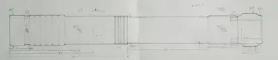
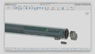
The chassis was designed in parallel with the electronics. I started off by measuring, drawing the schematic and annotating the dimensions for the hilt (Figure 3) in order to calculate the dimensions of the chassis. Then, I created a 3D-model of the hilt using Fusion 360 (Figure 4).
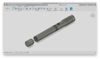
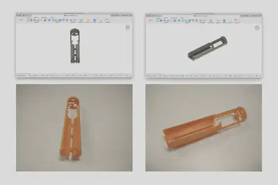
I also made 3D-models of the internal components (electronics, battery, speaker, etc.) to visualise them, to determine their placement and the design of the chassis (Figure 5). Figure 6 shows the 3D-model of the chassis and the resulting 3D-printed chassis.
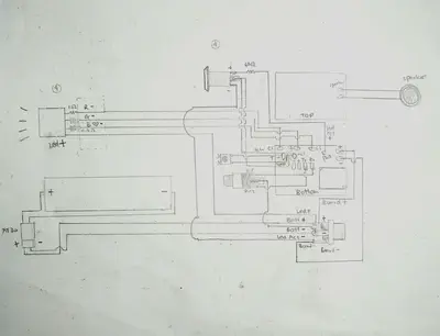
Electronics
I tested the wiring, electronics and components part by part before soldering them together and assembling them with the chassis and hilt. I mainly followed the wiring guides in the PRIZM v4 controller user manual. Figure 7 shows the wiring diagram which I drew as a reference while soldering.
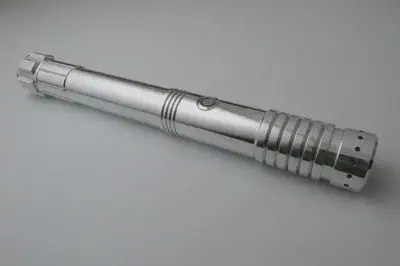
Gallery
Samantha Chan
Postdoctoral Fellow
I create wearable, AI and digital interfaces to enhance human cognition and memory at the MIT Media Lab.